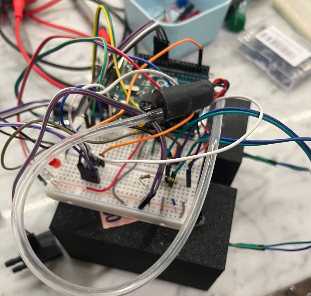
New regulatory monitors can cost up to 17 grand. This means that DC only has a handful of them, spread thin across a city where air quality varies block by block. So I built a low-cost monitor from scratch, inspired by a design from a UC Berkeley paper one of my mentors, Dr. Hsieh, sent me, and I adapted it to monitor air in DC.
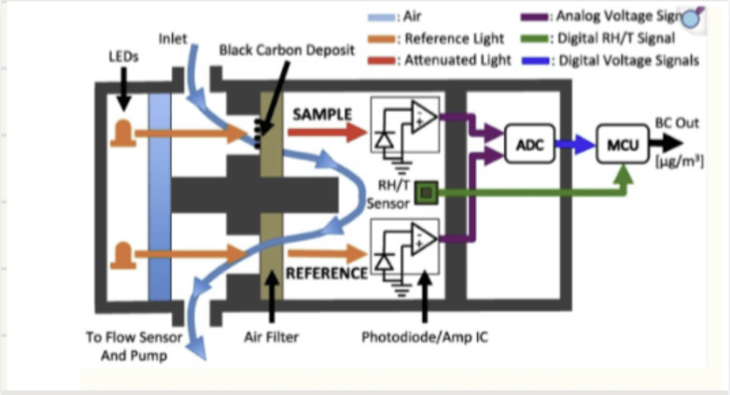
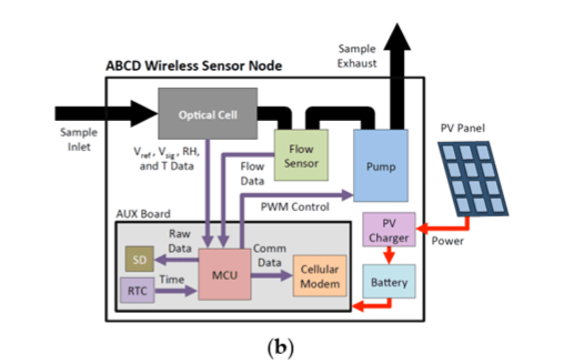
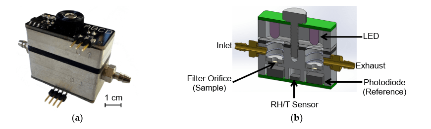
What’s inside:
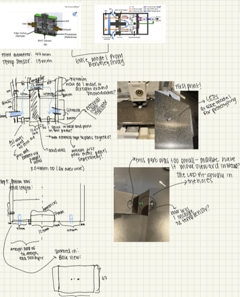
At the heart of the monitor is a simple optical principle: black carbon particles absorb light. Pull air through a filter, shine light through it, and measure how much gets through. Less light means more soot has collected on the filters.
The hardware breakdown:
FDS100 photodiodes: light sensors that measure attenuation through the filter
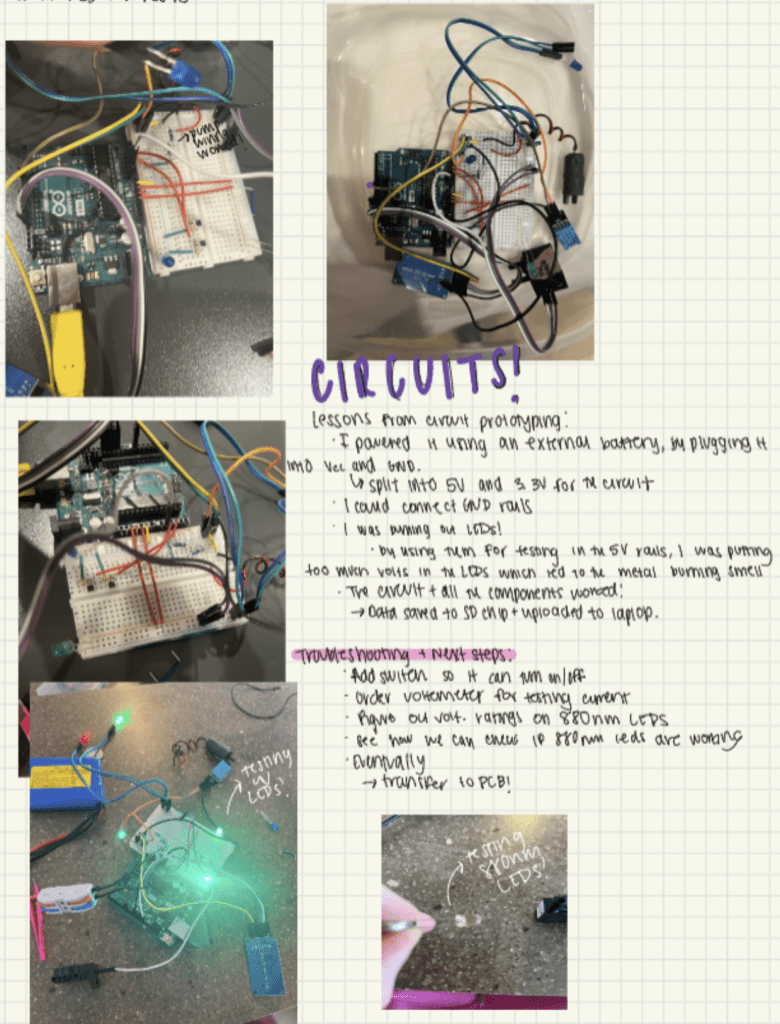
DS321 real-time clock (RTC): timestamps every reading
880nm LEDs: 880nm is the wavelength at which black carbon absorbs light.
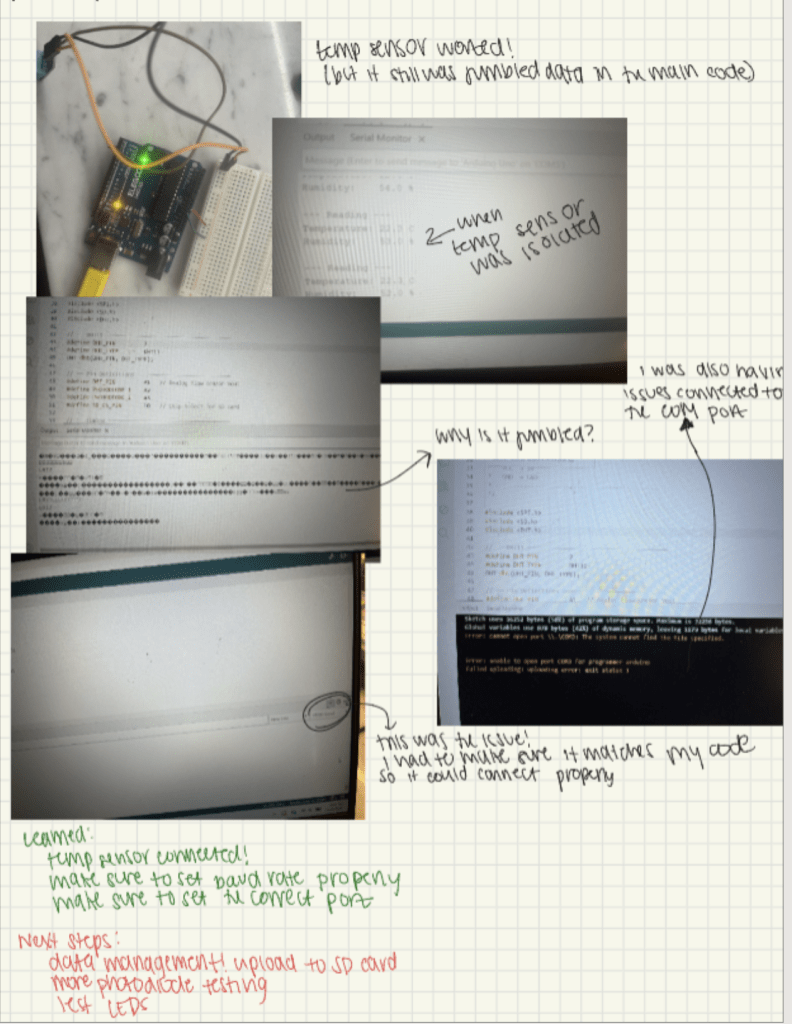
DHT11: tracks temperature and humidity, since both affect sensor readings and need to be corrected for.
D6F flow sensor: measures the airflow being pulled through the filter, which is essential for calculating the black carbon concentration.
SD card logging: stores data.
Arduino Uno: a processor to manage the data and voltage.
Schwartzer/135 FZ: air pump.
3D Printing:
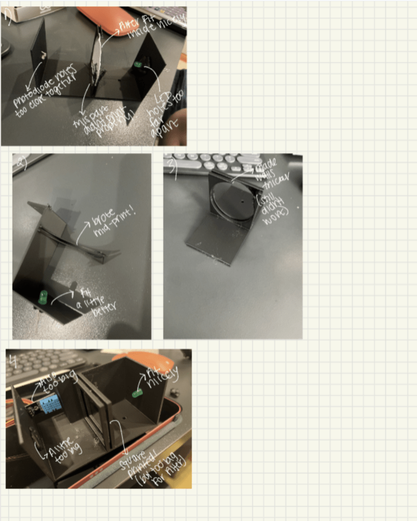
The first step was figuring out how to adapt the design such that it could be 3D printed.
Circuits:
Coding:
The final monitor: